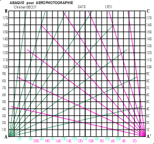
Preliminary:
It
is necessary to evaluate the distance from anchoring the
line to the photographic target.
The angle between the
kite line to the rig and the ground shall be known.
The length of line released from the rig to the anchor must
be controlled.
Method:
It is worked in 4 steps:
1st step:
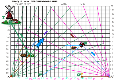
Set the angle of the
direction of the target AT with the wind/kite line direction
(blue arrow).
Place the sheet horizontally and aim
the target and the kite line. Choose either AB or A'C lines
as target direction depending if wind is on the right or on
the left of this direction. In this example, it is shown on
the right at 40°.
Set the distance from anchor A to
the target T along the line AB.
2nd step:
Determine the place
where the rig should be positioned to shot the picture. This
is the place shown as G on the wind direction.
From G, draw
the line GT to the target.
Measure the angle AG-GT which
is the pan angle of the camera.
On the example, this is 105°.
3rd step:
From A', draw the angle
ground / kite line to the rig. On the example, it is 50°
Measure the distance AG on the wind line, and draw A'G' equal
to AG on the horizontal ground line A' towards A.
From G'
draw the perpendicular which cut the kite line at the rig place
R.
Measure A'R which gives the length
of kite line to release between the rig and the anchor.
On the example, A'R is 110
4th step:
Measure the distance
GT; this is 100 on the example.
On the line A'A draw the
distance G'T ' equal to GT.
Draw the line RT '.
Measure
at R the angle between RT ' and the horizontal line. This is
the tilt angle of the camera.
On the example, this is 35°.
Conclusion:
This method requires
only simple tools.
When known, it needs only 3 minutes
to determine the necessary rig settings.
With the
field angle of the lens drawn on a transparent plastic board,
a more precise setting of pan and tilt angles lead to a better
arrangement of the picture. |

