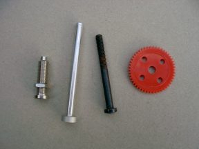
PAN  AXLE  and GEAR


The pictures herein are self-explanatory. The sleeve Ø 6 mm, threaded, is the main part of the assembly. The inside hole Ø 4 mm is convenient to receive the axle through it.
To get this sleeve is easy: Recover a bicycle tube-valve, or an electric connecting plug, and prefer a non isolated one.
On bicycle valve, the end must be cut and filed to get the Ø 4 mm hole free on its entire length
For the axle, use a stud, or a bolt Ø 4x40 mm not threaded entirely. (aluminum stud, titanum or steel bolt).
The remaining part of the assembly has no difficulty.
 
I'm using this assembly on all my craddles since many, many years, without any trouble.


  By means of experience, we must admit that a key point in the making of a craddle is the setting of the rotating vertical axle. It is not easy to design a mechanical device, simple, light, and strong. When checking many kaper's fabrications, it appears that the good solutions are few.
 
The red plastic wheel is glued on the axle with epoxy.
 
Last advise for motoring: the gearing down must be such that a turn is taking between 8 and 12 seconds.


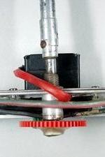
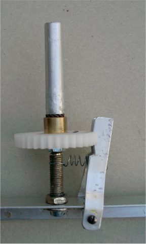
Here is the sleeve going through the frame of the rig, which is a L section

Under the plate there is a short aluminum tube to adjust the location of the gear wheel. The screw over the plate is hidden by the red sleeve of servo wire.


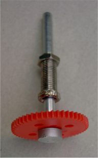
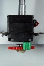
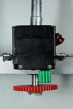
This is the side of the micro servo-motor. The ratio between the wheels is 10 to 40.

The axle is free to move 10 mm up and down. This makes possible to clutch the gear or have it free when holding up the cradle.


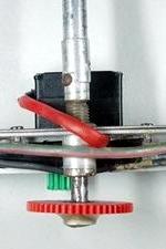
Over these devices, it can be either a Picavet or a pendulum suspension.


This aside is another way to have a quick and manual setting of the pan direction.

It also shows how easy it is to fit the pan axis that way, just drilling one hole in the frame.