|
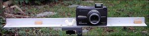
WITH A SINGLE
CAMERA
|
|
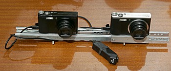
WITH TWO CAMERAS
|
|
|
|
|
|
|
|
|
|
|
|
|
|
|
|
|
The relief is maximum is at the nearest plan and the utmost when the background is further. The ideal thing is to have successive plans stacking one after the other and filling the space. A strong effect of relief between very distant plans is often producing a cardboard appearance like the backcloths in the theaters. |
|
Achieve a desired degree of relief at the first plan is controlling the base and the distance from the camera taken in account the remoteness of the background. The box "first plan" of the calculator determines the distance Dn calculated with the base B, the depth L and the choosen value SR. |
|
|
|
|
|
|
|
|
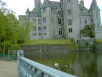
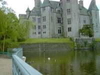
Because the two cameras are shifted, there are some circumstances where deep objects cannot be correctly visualized. See as example the two photographs aside, it will be impossible to juxtapose the two handrails, nevertheless, only 80mm separate these two views! |
|
|